फाइबरग्लास (जीएफआरपी) रीबार अब कोई दुर्लभ सामग्री नहीं रह गई है। संयुक्त राज्य अमेरिका में इसका उपयोग पुलों, पार्किंग गैरेजों, औद्योगिक फर्शों और यहां तक कि सामान्य आवासीय स्लैब और नींवों में भी दैनिक आधार पर किया जाता है। लेकिन एक व्यावहारिक प्रश्न अभी भी कई ठेकेदारों को परेशान करता है:
जीएफआरपी रीबार को वास्तव में कैसे स्थापित किया जाता है ताकि यह एसीआई 440.11-22 का अनुपालन करे और कंपोजिट के सभी लाभों को बरकरार रखे?
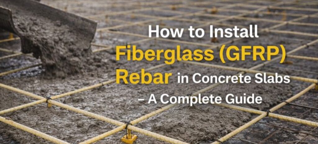
यह लेख अमेरिकी स्लैब और नींव में जीएफपी सुदृढीकरण के लिए एक व्यावहारिक स्थापना मार्गदर्शिका है: कटिंग, बांधना, बार स्पेसिंग, कवर, स्प्लिस, सामान्य गलतियाँ और कई विवरण जहां जीएफपी स्टील से अलग तरह से व्यवहार करता है।
महत्वपूर्ण: यह कोई डिज़ाइन गाइड नहीं है। सभी संरचनात्मक गणनाएँ (व्यास, रिक्ति, लैप लंबाई, बार लेआउट) लाइसेंस प्राप्त इंजीनियर द्वारा निर्धारित मानकों के अनुसार की जानी चाहिए। एसीआई 440.11-22 और स्थानीय भवन निर्माण संहिताएँ। यहाँ हम स्थापना पर ध्यान केंद्रित करते हैं।
जीएफआरपी को स्थापित करना स्टील रीबार के साथ काम करने से कैसे भिन्न है?
कार्यस्थल पर जाने से पहले, तीन मूलभूत अंतरों को समझना सहायक होता है।
वजन और कठोरता
- इस्पात का घनत्व: लगभग 7.8 टन/मी³
- जीएफआरपी का घनत्व: लगभग 1.9–2.2 टन/मी³ — लगभग स्टील के वजन का एक चौथाई.
व्यवहारिक रूप से इसका अर्थ यह है:
- जीएफआरपी के बंडलों को हाथ से ले जाना काफी हल्का होता है।
- भारी उपकरणों की आवश्यकता के बिना भी जाली और छड़ों को अधिक लंबाई में पहुंचाया जा सकता है।
- एक ही टीम एक ही शिफ्ट में अधिक सुदृढ़ीकरण स्थापित कर सकती है।
यांत्रिक व्यवहार के संदर्भ में, जीएफआरपी में माइल्ड स्टील की तुलना में 2-3 गुना अधिक तन्यता शक्तिलेकिन इसका प्रत्यास्थता मापांक लगभग है। 4-5 गुना कमसरल शब्दों में कहें तो: यह तनाव में बहुत मजबूत होता है, लेकिन विरूपण में थोड़ा अधिक लचीला होता है। साइट पर काम करते समय आपको यह स्टील की तुलना में थोड़ा लचीला और प्रत्यास्थ छड़ जैसा महसूस होगा।
संक्षारण और विद्युत व्यवहार
जीएफआरपी इसमें जंग नहीं लगता और यह बिजली का संचालन नहीं करता।, इसलिए:
- आपको "जंग से बचाव" के लिए अतिरिक्त कवर की आवश्यकता नहीं है; कवर बॉन्ड और अग्नि सुरक्षा संबंधी आवश्यकताओं द्वारा निर्धारित होता है।
- विद्युत चुम्बकीय रूप से संवेदनशील संरचनाओं (एमआरआई कक्ष, परीक्षण प्रयोगशालाएं, सबस्टेशन) में, जीएफआरपी गैर-चुंबकीय, गैर-चालक सुदृढ़ीकरण प्रदान करता है जहां स्टील स्वीकार्य नहीं है।
मोड़ने की सुविधा: केवल कारखाने में, कार्यस्थल पर नहीं।
स्टील के विपरीत:
- आपको साइट पर जीएफआरपी बार को नहीं मोड़ना चाहिए। इस सामग्री में स्टील की तरह प्लास्टिक प्रतिरोध क्षमता नहीं होती है। तेज मोड़ने से रेशों में सूक्ष्म दरारें पड़ जाती हैं और इसकी क्षमता नष्ट हो जाती है।
- सभी हुक, रकाब, एल- और यू-आकार के पुर्जे अलग से उपलब्ध कराए जाने चाहिए। कारखाने में निर्मित मुड़े हुए तत्वनिर्माता और इंजीनियर के बीच सहमत त्रिज्याओं के साथ (ACI 440.11-22 मुड़ी हुई GFRP छड़ों को इसी प्रकार मानता है)।
कंपोजिट-टेक समर्पित लाइनें सप्लाई करती है मुड़े हुए जीएफआरपी तत्व और स्टिरप्सइसलिए ठेकेदारों को परियोजना और संहिता के अनुरूप तैयार आकार प्राप्त होते हैं।
डिजाइन और कोड: इंस्टॉलर को क्या जानना चाहिए
डिजाइन की जिम्मेदारी इंजीनियर की होती है, लेकिन इंस्टॉलर को कई महत्वपूर्ण संदर्भों के बारे में पता होना चाहिए:
- जीएफआरपी रीबार के लिए मुख्य अमेरिकी कोड: एसीआई 440.11-22 – जीएफआरपी बार से प्रबलित संरचनात्मक कंक्रीट के लिए भवन संहिता की आवश्यकताएं.
- उत्पाद मानक: ASTM D7957 – ठोस GFRP बार के लिए यांत्रिक गुणों और सहनशीलता को परिभाषित करता है।
- कंक्रीट कवर, बार स्पेसिंग, लैप स्प्लिस और एंकरेज लेंथ सभी डिजाइन ड्राइंग में निर्धारित किए गए हैं, जो एसीआई 440.11-22 और स्थानीय भवन निर्माण संहिता पर आधारित हैं।
इस लेख में हम विशिष्ट जमीनी परिस्थितियों पर ध्यान केंद्रित करते हैं:
- स्लैब-ऑन-ग्रेड – औद्योगिक फर्श, लॉजिस्टिक्स और गोदाम के स्लैब, पार्किंग क्षेत्र, ड्राइववे।
- हल्के फाउंडेशन – कम और मध्यम ऊंचाई वाली इमारतों, उपकरण पैड, रिटेनिंग दीवारों के लिए स्ट्रिप और मैट नींव।
योजना बनाना: व्यास, रिक्ति और लेआउट
जीएफआरपी से बनी स्लैब और नींव के लिए, सबसे आम व्यास निम्नलिखित हैं: #3 (≈⅜” / 10 मिमी) और #4 (≈½” / 12 मिमी).
उदाहरण: गोदाम का फर्श या पार्किंग स्लैब
एक विशिष्ट अवधारणा (केवल उदाहरण के लिए, तैयार डिज़ाइन नहीं):
- स्लैब की मोटाई: 6 इंच
- सुदृढ़ीकरण: #3 GFRP @ 12″–18″ oc प्रत्येक दिशा में, दरार नियंत्रण रणनीति के आधार पर ऊपर या नीचे।
- कंक्रीट कवर: ऊपरी/निचली सतह से 1.5″–2″ (अंतिम मान ड्राइंग पर अंकित होना चाहिए)।
जीएफआरपी बहुत हल्का होने के कारण, इंस्टॉलर इसे आसानी से संभाल सकते हैं। 40-60 फीट की छड़ें या रोल-आउट जीएफआरपी मेश, जो उपयोग करते समय विशेष रूप से सुविधाजनक होता है। कंपोजिट-टेक मेश उत्पादन लाइनें जो जाली को चौड़े रोल में सप्लाई करते हैं।
भंडारण और तैयारी स्थल पर ही की जाएगी।
कंक्रीट के संपर्क में आने से पहले ही सामग्री को नुकसान से बचाने के लिए:
- बंडलों को डनेज पर स्टोर करेंसीधे जमीन पर नहीं।
- लंबे समय तक पराबैंगनी किरणों के संपर्क में रहने से बचाएं यदि भंडारण कई हफ्तों से अधिक समय तक करना हो, तो अधिकांश निर्माता छड़ों को ढकने की सलाह देते हैं।
- ऊंचाई से बंडलों को गिराने से बचें - जीएफपी मजबूत होता है, लेकिन स्थानीय प्रभाव से सतह पर खरोंच आ सकती है और रेशों को नुकसान पहुंच सकता है।
फाइबरग्लास रीबार को कैसे काटें
स्टील के लिए डिज़ाइन किए गए मानक बोल्ट कटर और हाइड्रोलिक कैंची उपयुक्त नहींवे कंपोजिट को कुचलकर उसकी परतें अलग कर देते हैं। उपयोग:
- कट-ऑफ आरी के साथ हीरा या अपघर्षक डिस्क, या
- छोटे-मोटे समायोजन के लिए, कार्बाइड के दांतों वाली एक हाथ से चलने वाली आरी।
व्यावहारिक सुझाव:
- हमेशा पहने आँखों की सुरक्षा, धूल से बचाव का मास्क और दस्ताने कांच की बारीक धूल आंखों, त्वचा और फेफड़ों में जलन पैदा कर सकती है।
- काटने से पहले छड़ को मजबूती से पकड़ लें ताकि कंपन कम हो और कटाई सीधी रहे।
- काटने के बाद, बार के सिरे को हल्के से रेत से घिस लें। एमरी क्लॉथ या सैंडपेपर का इस्तेमाल करने से इसे कपलर में डालना आसान हो जाता है और लकड़ी के टुकड़े चुभने का खतरा कम हो जाता है।
क्या जीएफआरपी छड़ों को साइट पर मोड़ा जा सकता है?
संक्षिप्त जवाब: नहीं.
- साइट पर कोल्ड बेंडिंग करने से आंतरिक फाइबर क्षति होती है जो अदृश्य होती है, लेकिन छड़ को गंभीर रूप से कमजोर कर देती है।
- सभी हुक, रकाब और शेप बार अवश्य होने चाहिए फ़ैक्टरी-मुड़ा हुआ नियंत्रित परिस्थितियों में और ACI 440.11-22 तथा निर्माता के डेटा की त्रिज्या सीमाओं के भीतर।
जब आपको बेंड्स की आवश्यकता हो, तो बस उन्हें बार शेड्यूल के हिस्से के रूप में ऑर्डर करें। कम्पोजिट-टेक के ग्राहक समर्पित उपकरणों पर विभिन्न प्रकार के आकार तैयार करवा सकते हैं, जिससे साइट को तैयार-टू-प्लेस एलिमेंट्स प्राप्त होते हैं।
फाइबरग्लास रीबार को बांधना और फिक्स करना
किसके साथ बांधें
100% सुदृढ़ीकरण को गैर-धात्विक और जंग-मुक्त रखने के लिए:
- उपयोग प्लास्टिक या कंपोजिट टाईनायलॉन ज़िप टाई या विशेष गैर-धातु क्लिप।
- आक्रामक वातावरण में, मानक काले एनील्ड तार से बचें - यह एक ऐसे सिस्टम में स्टील को वापस शामिल कर देता है जिसे जंग-मुक्त माना जाता था।
टाई रिक्ति
अधिकांश स्लैब और मैट सुदृढ़ीकरण में, यह पर्याप्त होता है:
- परिधि के चारों ओर प्रत्येक चौराहे को बांधें, और
- मैदान में हर दूसरे चौराहे को चेकरबोर्ड पैटर्न में बांधें।
जीएफआरपी इतना हल्का होने के कारण, एक अतिरिक्त जोखिम भी है: जाली ऊपर की ओर "तैरती" हुई कंक्रीट डालते समय। इससे बचने के लिए, निम्न का उपयोग करें:
- प्लास्टिक/मिश्रित कुर्सियाँ और स्पेसर सही ऊंचाई का,
- कंक्रीट के जमने तक छड़ों को अपनी जगह पर रखने के लिए पर्याप्त मात्रा में रस्सियाँ।
कवर और बार स्पेसिंग
अंतिम मान इंजीनियर द्वारा दिए जाते हैं, लेकिन सैद्धांतिक रूप से:
- आंतरिक स्लैब और फर्श के लिए, कंक्रीट कवर अक्सर इस सीमा में होता है 1.5″–2″जमने-पिघलने और बर्फ पिघलाने वाले नमक के संपर्क में आने वाली बाहरी स्लैब के लिए, कवर अधिक (2 इंच+) हो सकता है।
- स्लैब-ऑन-ग्रेड के लिए सामान्य बार स्पेसिंग निम्न सीमा में आती है: केंद्र पर 12″–18″यह स्लैब की मोटाई, भार और दरार की चौड़ाई की सीमा पर निर्भर करता है।
क्योंकि जीएफपी का मॉड्यूलस स्टील से कम होता है, इसलिए डिज़ाइनर आमतौर पर दरारों की चौड़ाई को स्टील-प्रबलित कंक्रीट के समान सीमा में रखने के लिए रिक्ति और/या बार के आकार को समायोजित करते हैं। साइट पर आपका एकमात्र काम यह है कि... रेखाचित्रों में दिए गए अंतराल और आवरण का ठीक से पालन करें।.
स्प्लिस, लैप लेंथ और एंकरेज
जीएफआरपी कंक्रीट के साथ स्टील की तुलना में अलग तरह से बंधन विकसित करता है, इसलिए:
- लैप स्प्लिस और डेवलपमेंट की लंबाई आमतौर पर स्टील की तुलना में अधिक होती है। ACI 440.11-22 बार के व्यास, कंक्रीट की मजबूती, आवरण और बार प्रोफाइल के आधार पर विशिष्ट समीकरण देता है।
- सामान्य तौर पर, जीएफआरपी के लिए कई टेंशन लैप स्प्लिस की लागत लगभग इतनी होती है। 40–60 बार व्यासलेकिन आपको हमेशा इंजीनियर द्वारा निर्दिष्ट मान का ही उपयोग करना होगा।
इंस्टॉलर के लिए उदाहरण: यदि ड्राइंग में #4 बार के लिए 50d लैप की आवश्यकता है:
- #4 का व्यास ≈ 0.5 इंच
- 50 × 0.5 इंच = 25 इंच लैप की लंबाई।
कुछ इंच की बचत सिर्फ अंदाजे से न करें। जीएफपी स्टील की तरह लचीला नहीं होता; मजबूती और दरार नियंत्रण के लिए पर्याप्त विकास लंबाई अत्यंत महत्वपूर्ण है।
औद्योगिक फर्श और गोदाम स्लैब के लिए स्थापना संबंधी विशिष्ट विवरण
दरार नियंत्रण
औद्योगिक फर्शों के लिए मुख्य चिंताएँ ये हैं: दरार की चौड़ाई और सतह की समतलताअंतिम बेंडिंग स्ट्रेंथ नहीं। GFRP यहाँ बहुत अच्छा प्रदर्शन करता है क्योंकि:
- सूक्ष्म दरारों की उपस्थिति में भी इसमें जंग नहीं लगता।
- इसे जंग से बचाने के लिए अतिरिक्त आवरण की आवश्यकता नहीं है, केवल यही पर्याप्त है।
- इससे सतह पर जंग के धब्बे या दरारें नहीं पड़तीं।
क्रू के लिए इसका मतलब यह है:
- बार स्पेसिंग को गंभीरता से लें, खासकर निर्माण और आरी से काटे गए जोड़ों के साथ।
- जीएफआरपी मेश रोल का उपयोग करते समय, उन्हें सावधानीपूर्वक खोलें और ग्रिड को इस प्रकार संरेखित करें कि रिक्ति डिज़ाइन के अनुसार बनी रहे।
कंपोजिट-टेक मेश लाइनें आपूर्ति करती हैं रोल में जीएफआरपी जालजिसे बहुत बड़े क्षेत्रों में बहुत जल्दी बिछाया जा सकता है, जिससे कठोर स्टील मैट को संभालने की तुलना में बिछाने का समय काफी कम हो जाता है।
जोड़ और डालना
हालांकि जीएफआरपी जंगरोधी है, फिर भी सिकुड़न और मुड़ने को नियंत्रित करने के लिए इंजीनियरड जॉइंट्स और सॉ कट्स की आवश्यकता होती है। जॉइंट ज़ोन में निम्नलिखित बातों का ध्यान रखें:
- का उपयोग करते हुए जीएफआरपी डॉवेल या कीज़ सुदृढ़ीकरण प्रणाली को पूरी तरह से गैर-धात्विक रखने के लिए स्टील डॉवेल के बजाय।
- इन तत्वों के संरेखण और आवरण पर ध्यान देना महत्वपूर्ण है - ये फर्श के दीर्घकालिक प्रदर्शन के लिए महत्वपूर्ण हैं।
जीएफआरपी के साथ काम करते समय सुरक्षा और स्वास्थ्य
कुछ सरल नियम आपके कर्मचारियों को सहज बनाए रखने में मदद करते हैं:
- हमेशा उपयोग करें सुरक्षा चश्मे और श्वसन यंत्र काटते समय, कांच की बारीक धूल आंखों और फेफड़ों के लिए हानिकारक होती है।
- धूल के साथ त्वचा के लंबे समय तक संपर्क से बचें; बड़ी मात्रा में सामग्री काटते समय लंबी आस्तीन वाले कपड़े या हल्के ओवरऑल पहनें।
- धूल को हवा में फैलने से रोकने के लिए उसे वैक्यूम क्लीनर से साफ करें, न कि सूखी झाड़ू से।
गुणवत्तापूर्ण इंस्टॉलेशन की शुरुआत गुणवत्तापूर्ण रीबार से क्यों होती है?
यहां तक कि उत्तम स्थापना भी खराब गुणवत्ता वाली जीएफआरपी छड़ों की भरपाई नहीं कर सकती: अपर्याप्त राल प्रवेश, कमजोर बंधन, थर्मल शॉक से सूक्ष्म दरारें इत्यादि।
वहीं पर बार के पीछे उत्पादन उपकरण गंभीर स्थिति उत्पन्न हो जाती है।
कम्पोजिट-टेक लाइनें कई का उपयोग करें पेटेंटकृत प्रौद्योगिकियां जो इंस्टॉलर को सीधे प्रभावित करते हैं:
- रोविंग प्री-हीटिंग यह इस श्रृंखला का पहला मॉड्यूल है। यह कांच की सतह से अवशिष्ट नमी को वाष्पित करता है और अतिरिक्त सिलान को हटाता है, जिससे राल के लिए जगह बनती है और मैट्रिक्स-टू-फाइबर बॉन्डिंग में सुधार होता है।
- रेजिन बाथ में हम उपयोग करते हैं गर्भाधान के तीन चरण:
- वायवीय दबाव जो यांत्रिक रूप से राल को तंतुओं के बीच गहराई तक दबाता है;
- अल्ट्रासोनिक उपचार जो रेजिन को सबसे महीन तंतुओं में परिवर्तित करता है;
- एक विशेष ग्रिड अनुभाग जो रोविंग्स को संरेखित करता है, समग्र गीलेपन में सुधार करता है और अतिरिक्त राल को हटाता है।
- हमारा रिब-वाइंडिंग मॉड्यूल पूरी तरह से समायोज्य है – केवल कम्पोजिट-टेक सीटी-4 और सीटी-6 मशीनें उच्च लाइन गति बनाए रखते हुए लगभग किसी भी कोण पर पसलियों को लपेट सकती हैं, जिससे विभिन्न कोड और कंक्रीट मिश्रणों के लिए बॉन्ड का अनुकूलन संभव हो पाता है।
- इस प्रसंस्करण प्रणाली में दो ओवन शामिल हैं:
- ए लघु-तरंग अवरक्त बूस्टर जो छड़ के अंदर से बहुलकीकरण की प्रक्रिया शुरू करता है;
- एक द्वितीयक भट्टी जो सतह को जलाए बिना सुखाने की प्रक्रिया को पूरा करती है।
- हम उपयोग करते हैं दो-चरण शीतलनसबसे पहले तापमान के चरम को कम करने के लिए जबरन हवा का उपयोग किया जाता है, फिर शीतलन प्रक्रिया को पूरा करने और बहुलकीकरण को रोकने के लिए जल स्नान का उपयोग किया जाता है। इससे थर्मल शॉक और सतह पर सूक्ष्म दरारों से बचा जा सकता है, जो अक्सर तब होती हैं जब प्रतियोगी 200°C तापमान वाली छड़ को सीधे ठंडे पानी में गिरा देते हैं।
ये सभी विधियाँ कम्पोजिट-टेक के पेटेंट द्वारा संरक्षित हैं और अन्य मशीन निर्माताओं के लिए उपलब्ध नहीं हैं। परिणामस्वरूप:
- कंपोजिट-टेक लाइनों पर उत्पादित जीएफआरपी रीबार में स्थिर ज्यामिति, सटीक रिब प्रोफाइल और चिकनी सतहजिससे इसे मौके पर लगाना और बांधना आसान हो जाता है।
- यह उत्पाद लगातार अपेक्षाओं को पूरा करता है या उससे भी बेहतर प्रदर्शन करता है। एसीआई 440.11-22 और एएसटीएम डी7957 उपयुक्त कच्चे माल और प्रक्रिया सेटिंग्स के साथ उपयोग किए जाने पर मजबूती, बंधन और स्थायित्व की आवश्यकताएं - अमेरिकी बुनियादी ढांचे और भवन परियोजनाओं के लिए महत्वपूर्ण हैं।
जीएफआरपी रीबार इंस्टॉलेशन के लिए त्वरित ऑन-साइट चेकलिस्ट
काम के दौरान त्वरित स्मरण के लिए, आप इस लेख को एक संक्षिप्त चेकलिस्ट में बदल सकते हैं:
- चित्रों को पढ़ें बार के आकार, रिक्ति, कवर और लैप की लंबाई ACI 440.11-22 पर आधारित हैं।
- सही ढंग से संग्रहित करें – सूखा, ऊँचाई पर स्थित, दीर्घकालिक यूवी किरणों से सुरक्षित।
- सही ढंग से काटें – डायमंड/एब्रेसिव सॉ, पीपीई और बार के सिरों की हल्की सैंडिंग।
- साइट पर झुकें नहीं – केवल कारखाने में निर्मित मुड़े हुए तत्वों का ही उपयोग करें।
- गैर-धातु फास्टनरों से बांधें – प्लास्टिक/कंपोजिट टाई, चेयर और स्पेसर।
- उचित दूरी बनाए रखें और उसे ढक कर रखें। विशेषकर समतल सतहों पर और जोड़ों के आसपास।
- लैप की लंबाई का सम्मान करें – 40-60 दिन के लैप्स को "आँखों के आधार पर" कम न करें।
- एक विश्वसनीय जीएफआरपी निर्माता का चयन करें बार के साथ काम करना जितना आसान होगा, उतनी ही अधिक संभावना है कि उनका उत्पादन आधुनिक, उच्च गुणवत्ता वाले उपकरणों पर किया गया होगा।
यदि आप इन नियमों का पालन करते हैं और इनके साथ काम करते हैं अच्छी तरह से निर्मित जीएफआरपी रीबार उन्नत उत्पादन लाइनों से, जैसे कि Composite-Techस्लैब और नींव में फाइबरग्लास सुदृढीकरण स्थापित करना आसान हो जाता है - और आपको जंग रहित, उच्च शक्ति वाली, टिकाऊ कंक्रीट संरचनाओं का पूरा लाभ मिलता है।
और अधिक जानें: